

PARTS FOR INSTALLATION:
The following wire routing and gauge mounting are recommended (and where we found the most convenient locations). You are free to mount the gauge and run the wiring in any location you prefer, the provided power wiring and ground should be long enough to reach many locations. You can also add on to any wiring if necessary.
Disconnect your negative battery terminal before proceeding.

1. Remove the engine cover/air box. This will make getting to the sensors much easier. In order to access the ignition power, you can also remove the battery and battery tray (caution, the ECU is attached to the back of the battery tray).
2. Below are the sensors we will be locating and working with:


2. Once the Vaitrix sensor harness is connected to the MAP sensor, you will need to find a place for the wiring to pass through to the cabin. This wire will run all the way to the gauge and connect at the back of the gauge.
3. Next, mount the gauge. The gauge wiring can run easily off the side of the dash and through the trim in the door jam, but you can put the gauge any place you desire (including in the stock gauge pod, shown below).

4. The second harness for the gauge contains wiring (red, yellow, blue, and black). We will not be using the blue wire. The red wire connects to a 12V battery source for the gauge memory. The yellow wire will connect to ignition power, and the black is for a reliable ground.
5. First connect the red 12V power wire, we recommend the battery (below).

6. Next, connect your ignition power source (yellow wire). We recommend the wiring cluster in front and below the battery (see below). Use the red positap.

7. Ground the ground wire onto the negative battery terminal.

8. Reconnect your battery, and turn on the ignition. The gauge should power on, and then read near zero. If the gauge is flashing alternately, this means you need to double check your connector at the sensor or power/ground for a solid connection.
]]>PARTS FOR INSTALLATION:
Remember to disconnect your negative battery terminal before proceeding with installation.

1. Remove the engine cover/air box. This will make getting to the sensors much easier. In order to access the ignition power, camshaft sensor, and boost pressure sensor on the charge pipe, you can also remove the battery and battery tray (caution, the ECU is attached to the back of the battery tray).
2. Below are the sensors we will be locating and working with:
A.
B.

C.

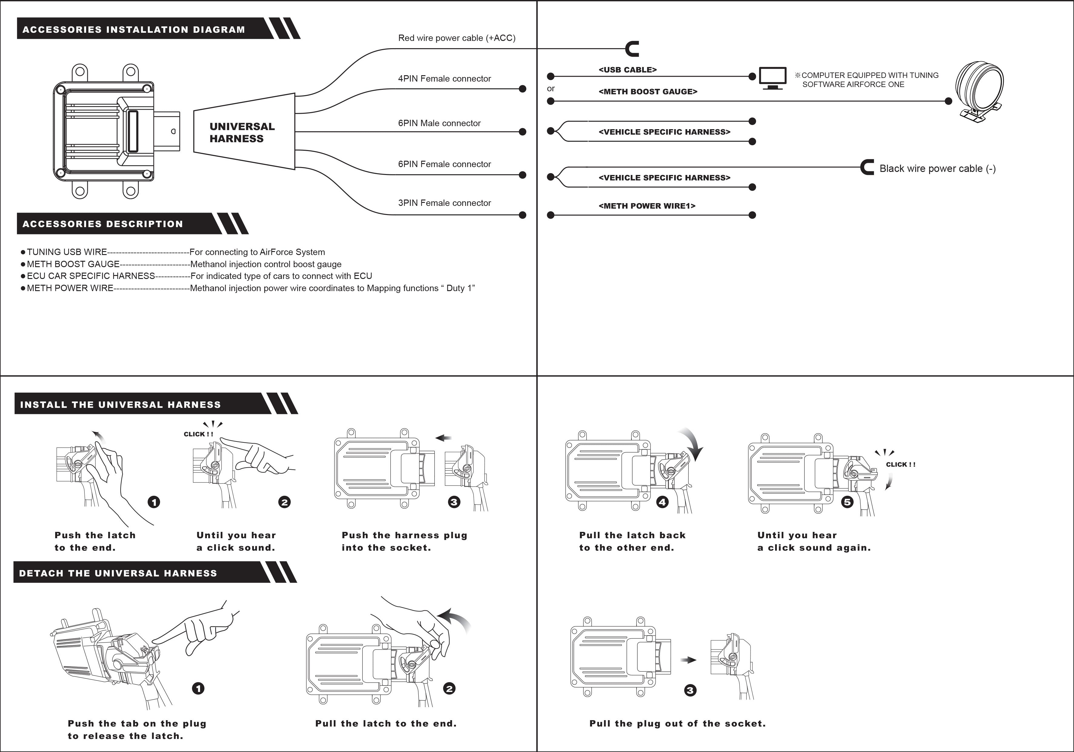
3. The harness and connectors that attach to the factory sensors are apart of the vehicle specific harness. This harness connects to the universal harness for the Booster ECU.
Once you have mounted the Booster (we recommend either on the back of the battery on the ECU, or on the fuse box in the engine bay), you can connect the vehicle specific connectors to the universal harness. These connectors only attach one way, but make sure you match up the correct attachments.

4. After mounting the Booster ECU, and connecting the vehicle specific harness to the universal harness on the Booster, you need to find ignition power for the red power wire coming from the universal harness. We recommend the wire below, which is located down and in front of the battery. Use the posi tap to connect to this power source.
5. On the camshaft sensor connector harness, there is also a ground wire. This needs to be connected to a reliable ground. We recommend the negative battery terminal.
6. On the universal harness, there's a 4 pin connector and 2 pin connector that have not been used, and are shorter in length. These are for the bluetooth module. Take the bluetooth module and connect to the two together. Route the bluetooth module to a location that will deliver strong signal (do not place below large components or parts of the engine).


8. Now reconnect your battery, and turn on the ignition. Ensure no CELs or DTCs are present. The most common lights to see are codes for barometric pressure and sensors. If this is the case, double check your connections and ensure your power source is well connected.
]]>
]]>

