
Configure your vehicle
| INSTALL | BOOSTER ECU: Alfa Romeo Giulia/Stelvio 2.0L

The following guidelines are instructions for installation of the VAITRIX BOOSTER ECU for all ALFA ROMEO Giulia and Stelvio 2.0L equipped vehicles.
PARTS FOR INSTALLATION:
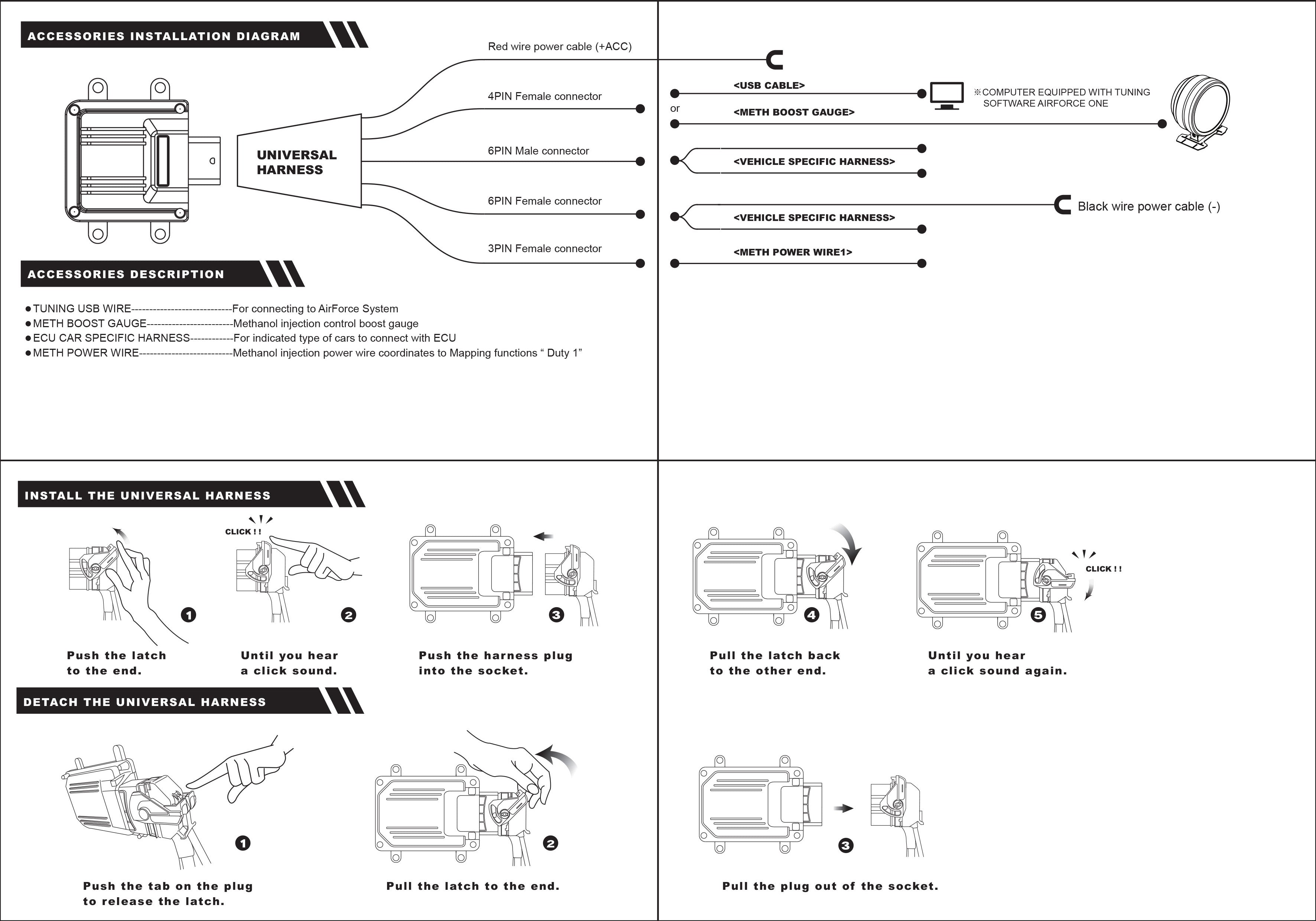
- - Vaitrix BOOSTER ECU
- - Universal Harness
- - Vehicle Specific Harness plugin
- - Red positap
- - 3M sticky pads for mounting
- - USB Tuning cable or Bluetooth Module (if applicable)
The following wire routing and mounting points are recommended (and where we found the most convenient locations). You are free to mount the unit and run the wiring in any location you prefer, the provided power wiring and ground should be long enough to reach many locations. You can also add on to any wiring if necessary.


Make sure to disconnect the battery before working with the engine sensors on the car.
1. Remove Engine Cover. Loosen the (2) bolts at the front of the cover, and pull engine cover up and off.


2. Remove the side cover. To do this, remove the (2) bolts near the top, and pull up and out. This needs to be removed in order to more easily access the MAP and Boost Pressure Sensors.

3. Now you will take the vehicle specific harness and begin connecting to sensors on the car.
There are (2) parts to the vehicle specific harness. One harness connects to both the MAP sensor and Boost Pressure sensor for boost readings. The other harness connects to the Cam Position sensor, and has a black wire for connection go a ground.
Below is the sensor locations:
A. MAP sensor
B. Boost Pressure sensor
C. Cam Position Sensor (located down the firewall and behind the downpipe shielding.

A. MAP Sensor

B. Boost Pressure Sensor (located on charge pipe, near the throttle body)

C. Cam Position Sensor

4. Connect the ground wire attached to the cam position sensor harness to a solid ground location, there are many in the engine bay.
5. Connect the vehicle specific harness connections to the universal harness, which will lead back to the Booster ECU. Again, this connections only fit one way and are all different, so it's difficult to get them mixed up.

6. Mount the Booster ECU using the 3M pads to the location of your choice. We recommend somewhere on the passenger side of the engine bay for ease of routing the wiring, etc.
7. Next, you will need to connect the red power wire from the Booster ECU to a source of ignition power. The best place to take ignition power from inside the engine bay is on the ignition wiring harness, located just behind the ECU near the airbox/intake air filter.
Take the provided red positap, and positap this wire into the black/orange wire on the ignition harness.


Once this is completed, you can begin to button up the engine bay.
The tuning map comes preloaded on the Booster ECU. You will want to re-connect the battery and turn on the ignition once the installation is complete. Make sure there are no CELs or error messages. If one appears, double check your connectors to ensure that they are all seated properly, and connected correctly.
If all is clear, you have completed this installation and are ready to take a test drive.
If using the bluetooth module, take the provided bluetooth module, and connect to the (2) bluetooth connectors on the universal harness of the Booster ECU. One connector is a (2) pin, the other is a (4) pin connector, they are near each other.
You can route the bluetooth receiver anywhere in the engine bay, but we recommend a place where it will not be too covered or buried, which will result in a weak signal.
