Configure your vehicle
| INSTALL | PLUG & PLAY BOOST GAUGE: Jeep Wrangler JL 2.0L

The following guidelines are instructions for installation of the VAITRIX Plug & Play Boost Gauge for all JEEP WRANGLER JL 2.0L equipped vehicles.
PARTS FOR INSTALLATION:
- - Vaitrix GEN2 Gauge
- - Vehicle Specific Harness plugin
- - Add a Fuse
- - Ring Connector
- - 3M sticky pads for mounting
- - Gauge Pod stand
- - Remote control
The following wire routing and gauge mounting are recommended (and where we found the most convenient locations). You are free to mount the gauge and run the wiring in any location you prefer, the provided power wiring and ground should be long enough to reach many locations. You can also add on to any wiring if necessary.


Make sure to disconnect the battery before working with the engine sensors on the car.
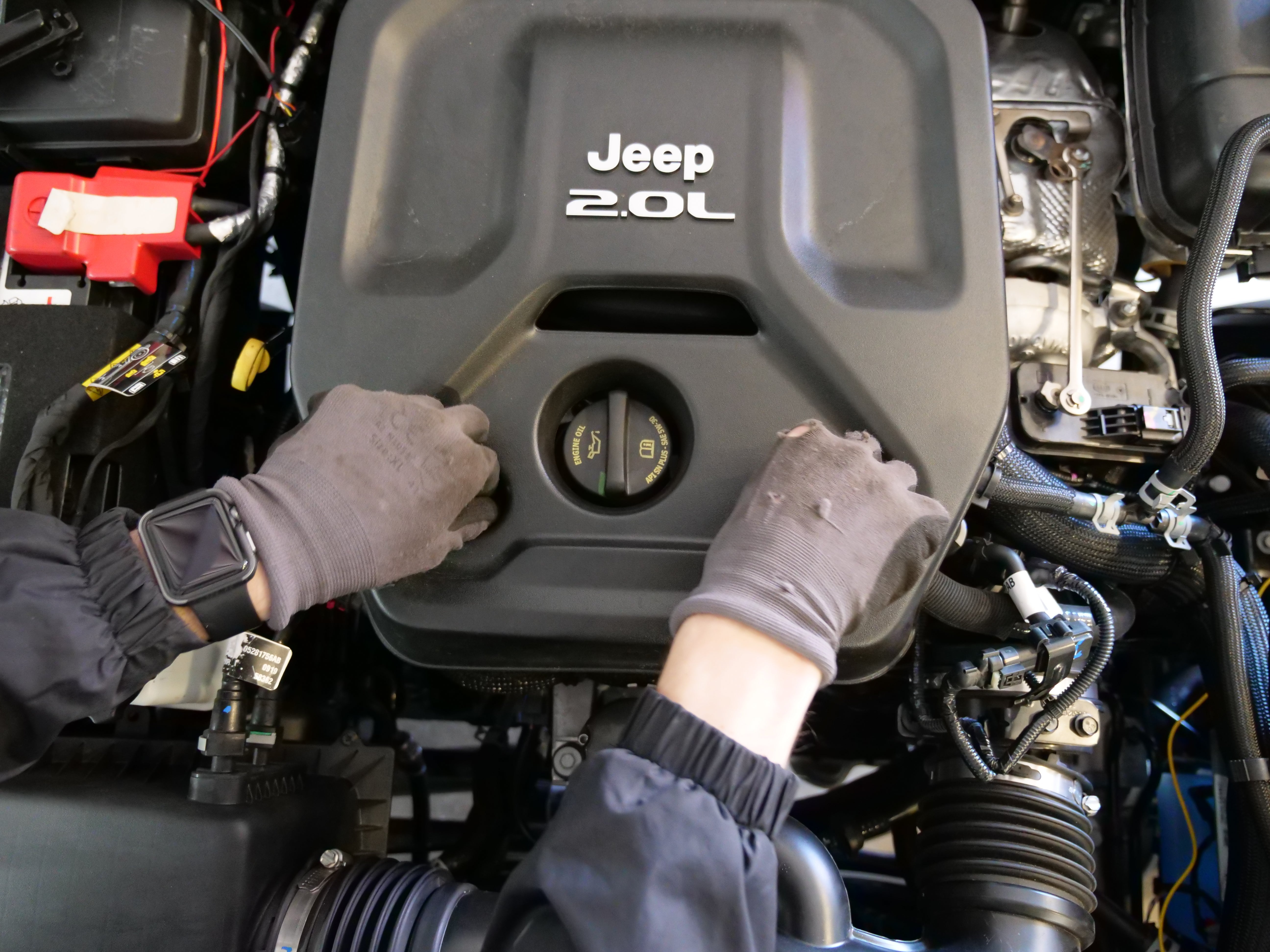
1. Remove Engine Cover. Loosen the (2) bolts at the front of the cover, and pull engine cover up and off.
2. Remove the side cover. To do this, remove the (2) bolts near the top, and pull up and out. This needs to be removed in order to more easily access the MAP Sensor.
3. Now you will take the Boost Gauge harness and begin connecting to the MAP sensor.
There are (2) parts to the gauge harness. One end connects to the sensor on the manifold, the other side of the harness connects to factory map sensor wiring harness.
NOTE: *If you are also installing the Vaitrix Booster ECU or have it already installed, the connectors must be installed in a specific order:
---
Factory Sensor------>Boost Gauge Connector (Male) >
>Boost Gauge Connector (Female)----------->Booster ECU connector (Male)>
>Booster ECU connector (Female)------------>Factory Connector (Male)
---
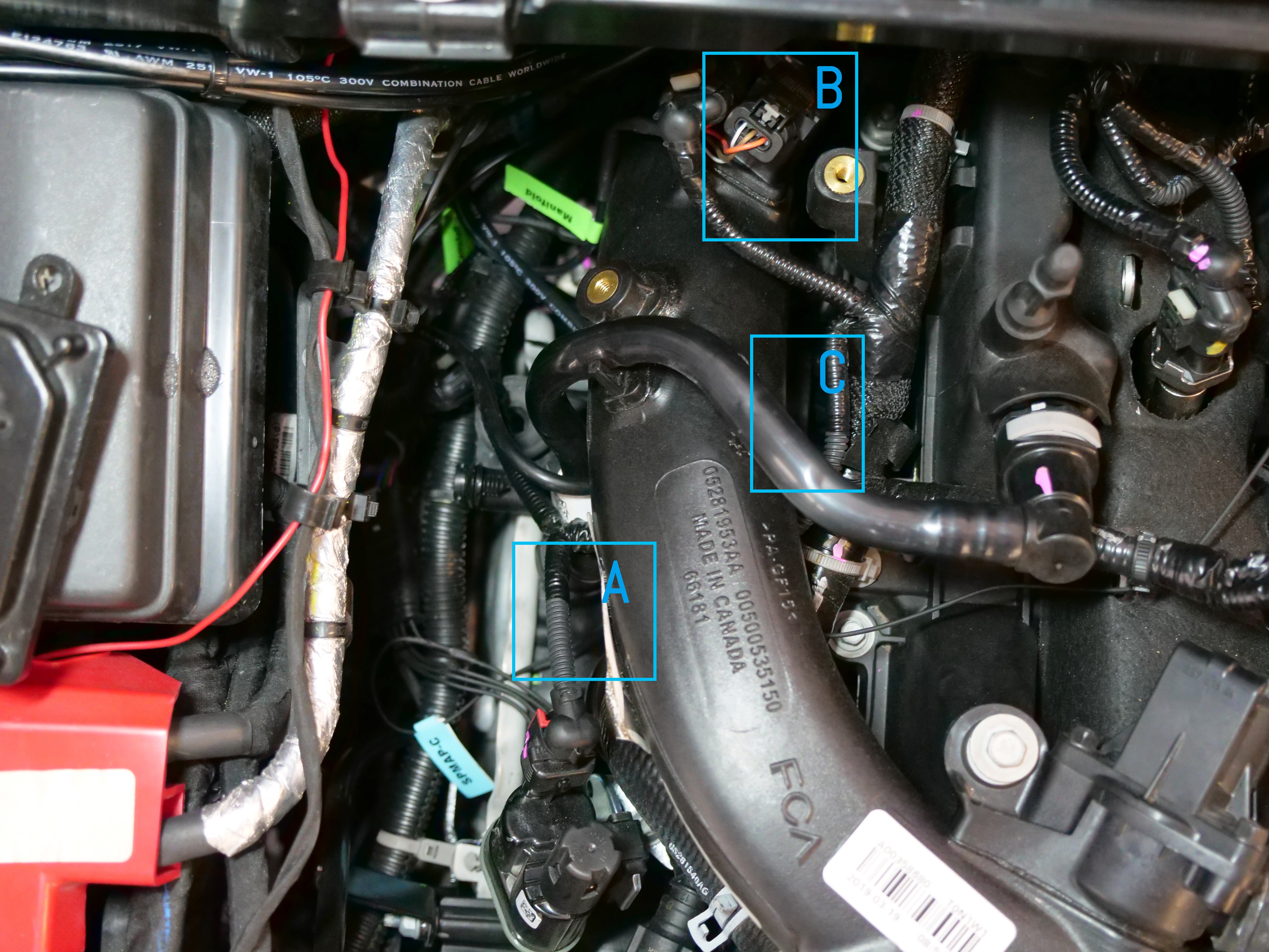
Below is the sensor location.
A. MAP sensor

A. MAP Sensor
Once the harness is connected to the MAP sensor, you can begin mounting the gauge and finishing the wiring.
There is a pass through on the firewall, drivers side near the corner. This is where you will pass your wiring through from the gauge to the engine and power sources.
The wiring will exit below the dash, can be fed up to the gauge. This is the mounting location we selected, but you can mount the gauge anywhere that is convenient.
4. The wiring portion of the gauge now needs to be hooked up to various ground and power sources in the engine bay. The wiring contains (4) different wires:
-Black: Ground
-Red: 12V power supply (for the gauge's internal memory)
-Yellow: Ignition power (used to power up the gauge)
-Blue: Power for interior lighting/lamp dimming when headlights are active (this is not used as the gauge has auto dimming)
5. Select any good ground point, and mount the ground wire. You can also use the negative terminal on the battery in the engine bay.
6. Connect the red power wire to 12V supply. It's okay if this mounting location has power all of the time, it's simply used to power the internal memory of the gauge to recall past data and set warnings/peaks. There is a mounting strip for 12V power choices on the positive side of the battery near the fuse box. We recommend this location.
7.
Next, you will need to connect the yellow ignition wire to a source of ignition power. The best place to take ignition power from inside the engine bay is inside the fuse box.
Use the provided add a fuse, and simply tap into the fuse location below.

Once this is completed, you can begin to button up the engine bay.
Make sure the harness wiring and power/ground source wiring is plugged into the back of the Boost gauge in the cabin.
You will want to arrange the plugs in the configuration below, or the signal may be backwards:

Once the battery is reconnected, you can turn on the ignition to test the gauge. If the gauge is blinking alternately between the needle and back light, you need to double check your connections and try again.


